This is the third and final post of a series about embedded firmware hacking and reverse engineering of an IoT device, a TomTom Runner GPS Smartwatch. You should start by reading part one and part two of this series.
I intended originally for this series to contain only three posts, and in order to achieve that, this post is longer than anticipated. Here is a table of contents for easier navigation:
- Finding familiar code: Using the exploit to exfiltrate the first bits of data from the firmware.
- Disassembling dumped code: First experiences with objdump to disassemble the recovered firmware fragments.
- Improving the dumping procedure: As a result of the reversing of a subroutine, we were able to improve the dumping routine dramatically and extract the full bootloader.
- AES key brute-force approach: Our first naive approach to recover the AES key by scraping the bootloader binary.
- Runtime debugging with QEMU: A couple of cool tricks to make it easy to do runtime debugging of the dumped bootloader, including QEMU+ IDA configuration, and creating a runnable ELF binary to debug natively in ARM systems with GDB.
- Final hurdles and MD5 verifications: After recovering the AES key we must be able to unpack and pack the firmware file. Some hurdles had to be overcome, and MD5 checksums were found and computed.
- Putting it all together: Here we demonstrate the capability of unpacking and modified an encrypted firmware file and successfully uploading it back to the device.
- Conclusion and next steps: Wrap-up for this series, ideas for future firmware modifications, upcoming TomTom watches, and other wearable devices.
Also, I’ve set up a github repository where I’ll keep the scripts and other tools / notes used in this research. It already contains some scripts but I intend to document it further in the next few days.
In the first post of this series I introduced you to the TomTom Runner. In the second one I showed you how I found a memory corruption vulnerability and took advantage of it to gain control over the execution flow and run arbitrary code on the watch.
If we were talking about a common architecture, such as a Windows PC or an Android Smartphone, we could have stopped there: Usually when researching bugs on these architectures the researcher usually leaves the “weaponization” of the code as an exercise to the reader (or does it privately for a profit, but that is subject for another post). My point is that on these systems the work stops when the bug is found and reliably exploited.
However, as I painfully learned, when exploiting a foreign platform (non standard software and hardware) it turns out that having arbitrary code execution is only the beginning of a long process.
01. Finding familiar code
We ended our last post showing how we could upload (and then execute) arbitrary code to the watch. We proved that we could execute the code by forcing a crash and reading the values of the registers on the crash log after the CPU faulted and the watch rebooted.
Crashlog - SW ver 1.8.42
 R0 = 0x00000000
 R1 = 0x00001337
 R2 = 0x00000013
 R3 = 0x00000037
 R12 = 0x00000000
 LR [R14] = 0x00441939 subroutine call return address
 PC [R15] = 0x00000000 program counter
 PSR = 0x20000000
 BFAR = 0xe000ed38
 CFSR = 0x00020000
 HFSR = 0x40000000
 DFSR = 0x00000000
 AFSR = 0x00000000
 Batt = 4192 mV
 stack hi = 0x000004d4
Since we don’t have access to the firmware, we don’t know a lot of things, such as addresses of library functions, how to open/write files on the EEPROM, how to write to the LCD or how to communicate using USB. Had we known those things, the process to dump the device’s firmware would be relatively straightforward.
The only obvious way to learn about the contents of the firmware is to load memory positions to registers and induce a crash so that the resulting crashlog contains the interesting values. This can be done with the following assembler code:
1
2
3
4
5
6
7
8
9
ldr r4, =0x00400000
ldr r0, [r4], #0x04
ldr r1, [r4], #0x04
ldr r2, [r4], #0x04
ldr r3, [r4], #0x04
ldr r12,[r4], #0x04
ldr lr, [r4], #0x04
mov r4, #0x00
bx r4
(I now know that most of these ldr can be optimized into a single ldmia instruction, but bear with me. I knew zero about ARM assembler when I started this project.)
What this code does is load the contents of address 0x00400000 into the 32 bits of r0, then the next 32 bits into r1 and so on. We even use the lr register, which usually holds the return address, because we don’t need to return from this code. Then we induce a crash by attempting to bx into 0x00000000 which will always fail on a Cortex-M4 (as explained on the last post).
Using this code we can extract 24 bytes of RAM or ROM every time we reboot the device. The actual process works like this:
- We craft our payload by assembling the instructions and inserting them into the correct region of the language file;
- We then upload the file to the watch;
- We unplug the watch from USB, wait 2-3 seconds for it to boot;
- We then proceed to the language menu and try to select a specific language. The device will crash and reboot;
- We plug the device back to the PC and read the crash log file containing the chosen bytes of RAM (or ROM).
This process must be repeated for ever 24 bytes we wish to extract from the device. I automated all the possible bits into a Python script, but the process involves plugging and unplugging the device’s USB connection to the PC and manually interacting with it.
After some practice I could do a “cycle” of this process in around 20 to 30 seconds. Since we know the firmware is around 400kb, extracting the whole of it would take around six days of constant device reboots and button mashing, without sleeping or eating. I don’t know about you but that doesn’t seem like a particularly fun use of my time :)
So we need to be very specific and find interesting bits of memory to dump and then analyze. I could only think of a good place to start: The code that was generating the crash log file. It checked all the boxes:
- It should be easy to find: Since the code must be called when there’s a hard fault of the CPU, it must be indexed in a table at a specific address;
- It should be simple and self contained: This code only needs to gather some information, and write it to a file on the EEPROM;
- It does what we want to do: This code should be able to write to a file on the EEPROM. We want to do this because it would enable us to dump the entire contents of firmware to the EEPROM.
How do we find the starting address for the hard fault routine? Looking at the Atmel datasheet for the MCU gives us what we need: The address for the routine is at the Vector Table, as shown here:
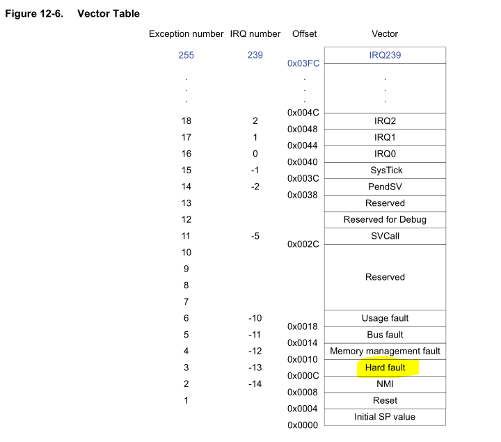
The Vector Table itself is mapped at address 0x00000000 on boot but it may be relocated. To find the current address of the Vector Table we can use the Vector Table Offset Register (SCB_VTOR), which is memory mapped at 0xE000ED08 as shown here:

So this code should get us the starting address for the fault handler:
1
2
3
4
5
6
7
8
9
10
11
12
13
14
15
16
17
18
19
.syntax unified
.thumb

/* Load VTOR address */
ldr r2, =0xE000ED08
ldr r3, [r2]

/* add offset to hardfault address */
mov r1, #0x0c
add r2, r3, r1

/* load hardfault address */
ldr r3, [r2]

/* halt and catch fire */
mov r4, #0x00
bx r4

/* RESULT: hardfault address is 0x0040bfa1 */
When executing this code on the device the value we get for r3 in the crash log is 0x0040bfa1, so we can assume that the hardfault handler code starts at 0x0040bfa0 (remember that the LSB is only for specifying Thumb mode).
Using some Python magic (script dump_script.py) we dump some bytes from this address and we get the main routine of the hard fault handler code.
02. Disassembling dumped code
Before I show you the recovered code we must arrange it in binary form in a way that it can be easily disassembled and analyzed. The easiest thing to do is to create a zero-filled file of 1 megabyte (our firmware is smaller than that). Then using Python we can start populating this file at the correct offsets, assuming that the base of the ROM is at address 0x00400000.
The script dump_script.py automates the whole process of dumping region “x” from the device and writing to this file (DUMP.bin).
We can disassemble the recovered code using objdump or IDA. Remember that, since we can only dump 24 bytes at a time, we’re going to be looking at incomplete code.
We can disassemble the code with objdump like so:
arm-none-eabi-objdump -D -s -b binary --show-raw-insn --prefix-addresses -EL --adjust-vma=0x00400000 -marm -M force-thumb -C DUMP.bin
Here is the beginning of our hard fault handler code:
1
2
3
4
5
0x0040bfa0 f01e 0f04    tst.w   lr, #4
0x0040bfa4 bf0c         ite     eq
0x0040bfa6 f3ef 8008    mrseq   r0, MSP
0x0040bfaa f3ef 8009    mrsne   r0, PSP
0x0040bfae f004 bedb    b.w 0x00410d68
At this point I did some Google searches based on the format of the crash log file and found this page, containing an example function authored by Joseph Yiu for a Cortex-M3/M4 fault handler function. Note the similarities of the the printf() outputs with the crash log file (shown at the beginning of this post), and especially the assembler function preamble, which is - byte for byte - the same code we extracted from the device.
1
2
3
4
5
6
7
8
9
10
11
12
13
.syntax unified
.cpu cortex-m3
.thumb

.global HardFault_Handler
.extern hard_fault_handler_c

HardFault_Handler:
  TST LR, #4
  ITE EQ
  MRSEQ R0, MSP
  MRSNE R0, PSP
  B hard_fault_handler_c
Code taken directly from the blog post from 2011. Note the similarities with the dumped code above
It seems we’re at the right place :)
03. Improving the dumping procedure
What I did next was to dump the main hard fault subroutine and replicate it in the exploit payload. The objective was to experiment changing the code in order to dump more bytes at a time. The hard fault routine is similar to the skeleton code by Joseph Yiu, but not the same:
- Obtains some more information regarding firmware version and battery levels;
- Opens a file on the EEPROM and writes to it (as opposed to the original code which writes to stdout);
- Reboots the device.
I had to do some static analysis and dump some parts of the code, but the main way of finding out what which subroutine did was to upload the modified code and run it directly on the device. Note that we don’t need to dump all the code, just the main routine. We call the other routines directly in ROM space. Remember that our goal here is to increase the amount of bytes that can be exfiltrated from the device each time. After some evenings I was somewhat successful. Here is the code I have for show:
1
2
3
4
5
6
7
8
9
10
11
12
13
14
15
16
17
18
19
20
21
22
23
24
25
26
27
28
29
30
31
32
33
34
35
36
37
38
.syntax unified
.thumb

push    {r0-r12, lr}    /* save registers and return address */
sub.w   sp, sp, #616    /* resize stack */

bl      fillup          /* fill stack with mem dump */

mov.w   r1, #512        /* arguments for write() */
add     r0, sp, #100
ldr     r7, =0x00410e39 /* call write() */
blx     r7

add.w   sp, sp, #616    /* shrink back stack */
pop     {r0-r12, lr}
bx      lr              /* return from exploit payload (END) */

/**** 'fillup' function populates the stack with memory *****/
fillup:
add     r4, sp, #100

/* first 8 bytes **must** contain the string "Crashlog" */
ldr     r7, =0x73617243
str     r7, [r4], #4
ldr     r7, =0x676f6c68
str     r7, [r4], #4

ldr     r7, =0x00408706 /* Starting address for the dump */
add     r4, sp, #108
mov     r3, #94
lp1:
    ldr     r8, [r7], #4
    str     r8, [r4], #4
    sub     r3, #1
    cbz     r3, end
    b       lp1
end:
bx lr                   /* return from 'fillup' function */
After a lot of trial and error I was able to identify a function at 0x00410e38 that I dubbed “write()”. This function takes two arguments: A pointer to a buffer and a size (lines 9-10). It then writes the buffer to the crash log file. The funny thing: It does not write more than 376 bytes and the first 8 must be the string “Crashlog” (see lines 23-26). Don’t ask me how I figured this out, as it was late in the evening (or early morning depending on how you look at it).
So I basically assembled this, loaded it into the watch and had a way to dump 376 bytes per device reboot, which was a vast improvement over the previous 24 byte limit.
With this script it was possible to dump the entire firmware in a reasonable amount of time. I started on address 0x00400000 and discovered that from this address to 0x00408000 we can find the device’s bootloader. In a matter of a few minutes (or around 90 device reboots) I was able to dump it entirely.
Since the bootloader is responsible for the flashing of the firmware file it should contain the AES key to decrypt it.
To recap, this is what we know so far regarding the firmware update procedure:

- Firmware is uploaded via USB to the EEPROM chip;
- Upon reboot, the bootloader checks if there’s a new firmware file on the EEPROM, and verifies if it’s valid;
- If valid, the bootloader decrypts and flashes the firmware on the Atmel chip (internal flash)
We know all this by looking at previous hints but also by analyzing the bootloader we dumped. I will focus next on analyzing the bootloader, both statically (looking at the code) and dynamically (emulating + debugging).
But first, a parentheses on trying a quick way to find the AES key to the encrypted firmware file.
04. AES key brute-force approach
Having dumped the entire bootloader we can conclude that:
- The bootloader must contain all the information necessary to decrypt the main firmware file, namely the AES decryption key;
- It is very likely the firmware is encrypted in AES ECB mode;
- We already have pieces of the main firmware’s plaintext;
- An AES key is a random byte string of length 128, 192 or 256 bits.
Armed with these pieces of information, my busticati friend pmsac (at toxyn.org) contributed to this mission with a small Python script that would sweep the bootloader and try and decrypt the main firmware file with every consecutive 16 byte string contained in the dumped bootloader (using a byte-by-byte sliding window over the entire bootloader file, not really caring for duplicates). There was also some care to make sure we were working on the right endianess. The resulting outputs were then passed through “ent” and the calculated entropy value was used to decide if a certain “plain text” was the desired output.
Unfortunately this did not produce a valid result. All of the resulting “plain texts” had no recognizable strings and still very high entropy, characteristic of encrypted/random byte sequences.
We must make sense of the bootloader and try to understand why the key was not immediately available.
05. Static analysis with IDA
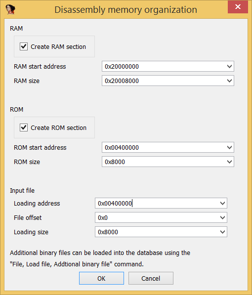
To load the dumped bootloader binary blob into IDA it’s just necessary to select ARM little endian architecture and base the file at 0x00400000, like the following picture shows:
The bootloader is not huge by any means (32kb), but since we already know what we’re looking for, it doesn’t make sense to lose time. Lets go find data structures which AES uses, such as S-Boxes:

There’s the S-Box :) Following code references to this array we get to the AES functions, and traversing back from those we finally arrive to a main routine which looks like the main firmware upgrade routine, at 0x004058d4. Here’s IDA’s graph view of it, just because it looks nice:
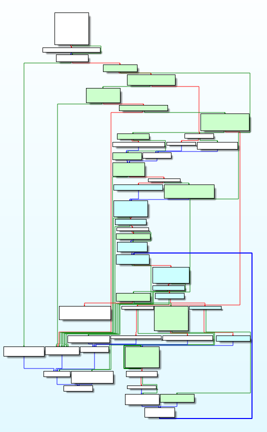
This looks like a nightmare to analyze, but remember: at this stage we’re just looking for something very simple: A reference to the AES key.
By now it’s important to talk about the basics of AES: AES uses three possible key sizes: 128, 192 or 256 bits. Before doing a single round of encryption, AES must do a computation called AES key expansion which basically takes the master key and creates additional separate keys derived from the original, to use in each AES round.
Using static analysis I could recognize the AES key expansion function at 0x00404618. Here it is being called early in the firmware upgrade routine:
 (I named the routines as I was recognizing them in IDA)
The routine takes two arguments, passed in r0 and r1 (ARM calling convention is helpful here: Arguments are almost always passed via registers), the arguments are the address for the original key (r0) and the size of the key (r1). We learn from this that:
- Key size is 128 bits (0x10);
- The key is stored in RAM at
0x2000001c.
There must be some code somewhere that’s loading the key in RAM before this code runs. We have to find it.
This was around the time that my limited experience doing static analysis kicked in. I simply could not guess anymore and had to see the code running.
Let’s talk a bit about getting this code into a debugger and doing some runtime analysis.
05. Runtime debugging with QEMU
Since we already have the code loaded into IDA Pro, it is a simple matter of using an emulator such as QEMU to emulate and debug the code.
This post was very helpful on the setup. There were some issues with QEMU, namely there is no QEMU ARM “machine” that emulates RAM at the 0x20000000 range. This was a problem that I had to overcome by creating breakpoints and manually “remapping” the RAM range to a different region at 0x02000000.
Later I was told about another (better) way to run QEMU to help debug this program, which is to run it in user mode. Basically I found you can run QEMU in three different ways:
- In kernel mode where you run a single kernel process that talks to the underlying virtual machine hardware directly;
- In VM mode where you set up a virtual OS environment, usually a Linux kernel and initrd image and filesystem, and then start the program to be debugged inside the VM environment;
- In User mode where you run QEMU in transparent fashion. For instance if you’re in a Linux x86 system and have a Linux ARM ELF binary you just need to run ./qemu
and it runs directly.
I found the third option very interesting. All that was needed was to create an ELF executable from the binary blob I had from the bootloader.
This can be done using the GNU linker. Documentation is pretty bad though, so I’ll leave here an example:
Main linker script (linker.ld):
ENTRY(_bl_start)

PHDRS
{
        text PT_LOAD AT (0x00400000) FLAGS (0x7) ;
        data PT_LOAD AT (0x20000000) FLAGS (0x7) ;
}

SECTIONS
{
        .text 0x00400000 : { *(.bootloader) } :text
        .data 0x20000000 : { *(.sram) } :data
        .note.gnu.build-id 0x0 (NOLOAD) : { *(.note.gnu.build-id) } :NONE
}
bootloader.s:
.section .bootloader, "ax"

.global _bl_start
.incbin "BOOTLOADER.bin"
.set _bl_start, 0x004000e5
sram.s (the sram_128k.bin file is merely a null filled file. This is necessary to make the ELF binary pre-allocate the RAM segment):
.section .sram, "awx"
.incbin "sram_128k.bin"
With these three files the ELF binary can be compiled like so:
gcc -static -c sram.s
gcc -static -c bootloader.s
gcc -static -nostdlib -T ./linker.ld -o bootloader.elf bootloader.o sram.o
The cool thing about this is that you can run this binary natively on a Raspberry Pi 2 (but not on the original rPi, because its CPU does not support the udiv instruction for integer division, which the Cortex-M4 uses).
The program will still segfault because it is attempting to read from memory mapped registers outside the RAM region. You can map these register addresses in a similar way to the way we allocated the RAM region, or you can simply step over the offending functions using GDB.
Tracing with GDB in IDA is very easy and you can see the RAM as it gets populated. Without bothering you with the details, here’s what I found out that was happening:
- Early in the bootloader execution the key is loaded from ROM into RAM. It’s actually at address
0x00406f0c - The AES key expansion routine at
0x00404618is called later and expands the key. However before the expansion is done, a single byte of the key is changed: The first byte of the key is set to 0x04!
We have the firmware key! I won’t post it here because of reasons (I have not consulted my lawyer yet). If you are worthy, with all this help you’ll get it pretty quickly :)
06. Final hurdles and MD5 verifications
Using AES ECB with the extracted key provided us with easily recognizable strings and ARM instructions. There was however a small hurdle, as the TomTom engineers did an additional obfuscation step: The first byte of each plaintext 16-byte block was off. This was easily spotted by looking at offsets containing ASCII strings.

Again, my friend pmsac managed to break this obfuscation before I had the chance to even try. There is a xor operation done on the first byte of each block with a rolling value ( incremented by 4 on each iteration and wrapping around at 0x80). Here’s the code to “demangle” the first byte of every plaintext block:
1
2
3
4
5
6
7
8
9
10
def xormask_blob(data):
   i = 0
   output = ''
   extra = 0
   while i < len(data):
      output = output + chr(ord(data[i])^extra) + data[i+1:i+bsize]
      extra += 0x4
      extra &= 0x7f
      i += bsize   # bsize is 16 bytes
   return output
The next step was to upload a modified firmware file into the watch. Using static analysis of the firmware upgrade routines I already knew there were two different MD5 verifications. But static analysis has its limits and I couldn’t tell exactly where and how the MD5 sums were verified.
Again my good and talented friends helped. João Poupino built a script that brute-forced a lot of different MD5 calculations, with both the plaintext and the ciphertext. Using this script we got to the following conclusions:
- The first 16 bytes’ block of the firmware file is a “poor man’s HMAC”: it’s the result of md5sum(ciphertext + encryption_key);
- In the plaintext there is a second md5sum() of the plaintext at the end of the code to be flashed. I believe it’s used by the bootloader to verify that the code has been correctly flashed.
07. Putting it all together
I did a small script that decrypts and encrypts a firmware file given its key. Most of the tools and techniques I used in this project are (or will be) published at my github here.
I did a small proof of concept by modifying a string inside the firmware file. Since almost every string you see when normally operating the watch is localized from an external language file (which we’ve already seen are easy to change without touching the main firmware), I had to look for something different: the Test Menu uses hardcoded strings, and I modified the one that originally said “Waiting for cmd”. The new string is much better, as you can see in the pictures.
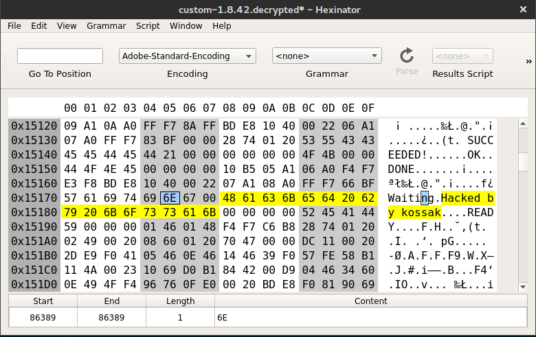
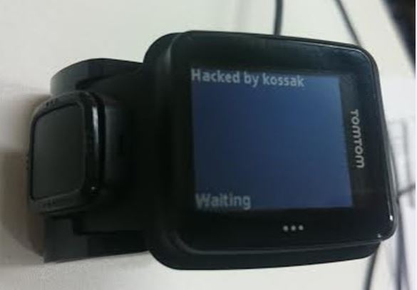
This is an innocuous modification but it proves it is now possible to write custom firmware for the TomTom Runner.
08. Conclusion and next steps
After doing all this and opening up the opportunity of creating custom firmware for this device, I really hope I manage to inspire someone to create something cool for this watch. I have some ideas already:
Port Linux!There’s not enough flash space or RAM to run ucLinux, let alone a full fledged Linux kernel.- Modify the existing firmware: Turning a TomTom Runner into a TomTom Multisport doesn’t seem particularly hard, as it seems it only verifies some values on the Bootloader region. The firmware is identical. Patching the firmware to always show the Multisport functionality doesn’t seem at all that complicated, but I haven’t spent time on that.
- Create a skeleton source tree from scratch: I’m still not sure, but the firmware seems based on FreeRTOS, an open-source OS. It should be feasible to reverse the hardware drivers (LCD, EEPROM) and recreate a basic firmware to serve as placeholder for an open-source alternative. This should allow for other fun uses for the hardware;
- A simple smartwatch with smart notifications;
- A wearable Ubertooth One! (this one would be my favourite, by far).
I will end this by giving a big thank you to everyone that helped me on this project, especially pmsac and João, who might have saved me from permanent insanity. I had a blast, learned quite a lot and hope to have contributed to the research community with these posts.
Regarding TomTom, I made sure I contacted them beforehand, letting them know about this issue. They acknowledged it and have been very polite, and have already implemented some changes to the latest versions of the Firmware. I hope further long term changes get implemented especially on their next line of products, to help mitigate this issue.
Also, I recently bought a new TomTom Spark and I may return to this later to see if the new models are that much different. We’ll see. It should be interesting to see if other smartwatches can be hacked this way. Interesting devices that I encourage people to look at: the Garmin Forerunner line, Polar sports watches and also the Pebble.
If you’re still reading, thank you! Tweet me at @lgrangeia and give me feedback and ideas for new projects.